
BAZIS CNC / CAD System
📊 Illustration diagram
From drawings / projects to the BAZIS CNC module
Activate BAZIS CNC in the 3D drawing environment

Activate BAZIS CNC in the project working environment

Select the control system “CAD System – DXF”
This is the standard DXF file generation mode for importing into Woodsoft Nesting.

Check “Favorite” so you do not need to select it again in future operations.
BAZIS CNC working interface / tab: Panel List
If the export configuration has already been set up, simply select the material types to be exported and click “Export”.

BAZIS CNC working interface / tab: Postprocessor
Tab 1: For the first operation, you need to load the configuration file CAD System Woodsoft.cncconfig from the download folder and load it using the folder icon as shown below.
Tab 2: Select a fixed output path to save the returned DXF files on your computer.

📥 Download sample DXF System configuration
🛠️Detailed explanation of configuration parameters
a. Basic parameters
General:

➕ Grain Direction Aligned with Machine Length
Ví dụ:
Set the grain direction of parts to align with the machine's length axis.
For example:
KDT machines using the Syntec control system: If the machine’s length is along the X-axis, choose “Grain direction along X-axis”
Typical Chinese CNC machines with Syntec controller: If the machine’s length is along the Y-axis, choose “Grain direction along Y-axis”
📌 Other settings should be configured as shown in the image (if there's an image to refer to).
Let me know if you'd like a diagram or visual reference created for this!

Milling: Set the parameters as shown in the image above.

Drilling Holes: Configure as shown in the image, or adjust the setting in "Process drilling holes with diameter greater than..." if your CNC machine does not have tools capable of processing small holes.
If the smallest drill bit installed in your CNC machine is 5 mm, then holes with diameters less than or equal to 5 mm cannot be machined. Set "Process drilling holes with diameter greater than 4" so that all holes smaller than 5 mm in your 3D model will not be included in the exported DXF file. This prevents errors during the Nesting process later.

Edge Banding Calculation: Configure as shown in the image below. 📌 Note: The drill hole coordinates are based on the original dimensions of the part before edge banding is applied.

Grooving (Xoi): Configure as shown in the image above.
📌 Note: The “Ignore grooving operations” setting can be used to exclude grooves that are not meant to be processed on the CNC machine, such as back-side scoring cuts or beveled edge details. This helps avoid unnecessary toolpaths during the Nesting process.
b. Technical Specifications

Operation: Tick the items you want to machine in the exported file.
Do not uncheck the side drilling option (to display horizontal drilling information on the label).

General: Set up as shown in the image, paying attention to the marked items.
c. Other parameters
d. Drilling hole configuration

A drilling hole has 2 parameters:
[DIAM]: Diameter
[DEPTH]: Drill Depth
To configure the drilling hole, use the character $ to separate these two parameters.
Specifically, the configuration is as follows:
For holes on the front side:
Z_[DIAM]$[DEPTH]For holes on the back side:
B_Z_[DIAM]$[DEPTH]

After setting all the parameters, click "OK" and move to the "Parts List" to export the DXF file: In the "Material" section, select the materials to be nested.

Select the necessary parts or all of them, then click the "Export" button to export the DXF file for the Nesting step.

The exported result includes:
A main folder for the order,
Subfolders divided by material,
And DXF files of each individual part inside the material folders.
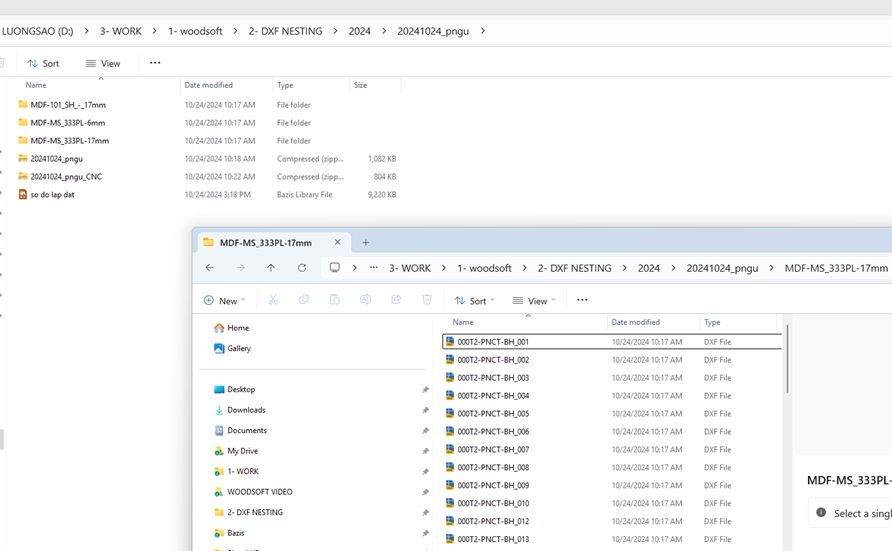
Compress the entire main folder into a single .zip file to prepare for the Nesting process on Woodsoft Nesting (you can use WinRAR or 7-Zip).
Last updated